COMPACT BATTERY DOOR
MECHANISM STUDY
A Comprehensive Mechanical Engineering Solution: From First-Principles Kinematic Analysis Through Iterative Concept Evaluation to a Final Bistable Push-Push Assembly for a Compact iPod-Style Consumer Electronics Battery Door.
CONCEPT SKETCHES
Hand-Drawn Mechanism Ideation — Iterative Path to Final
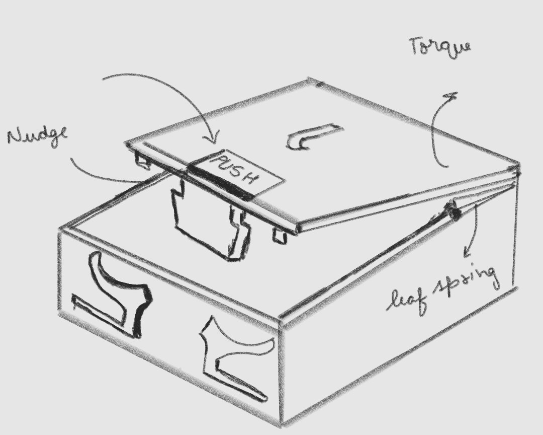
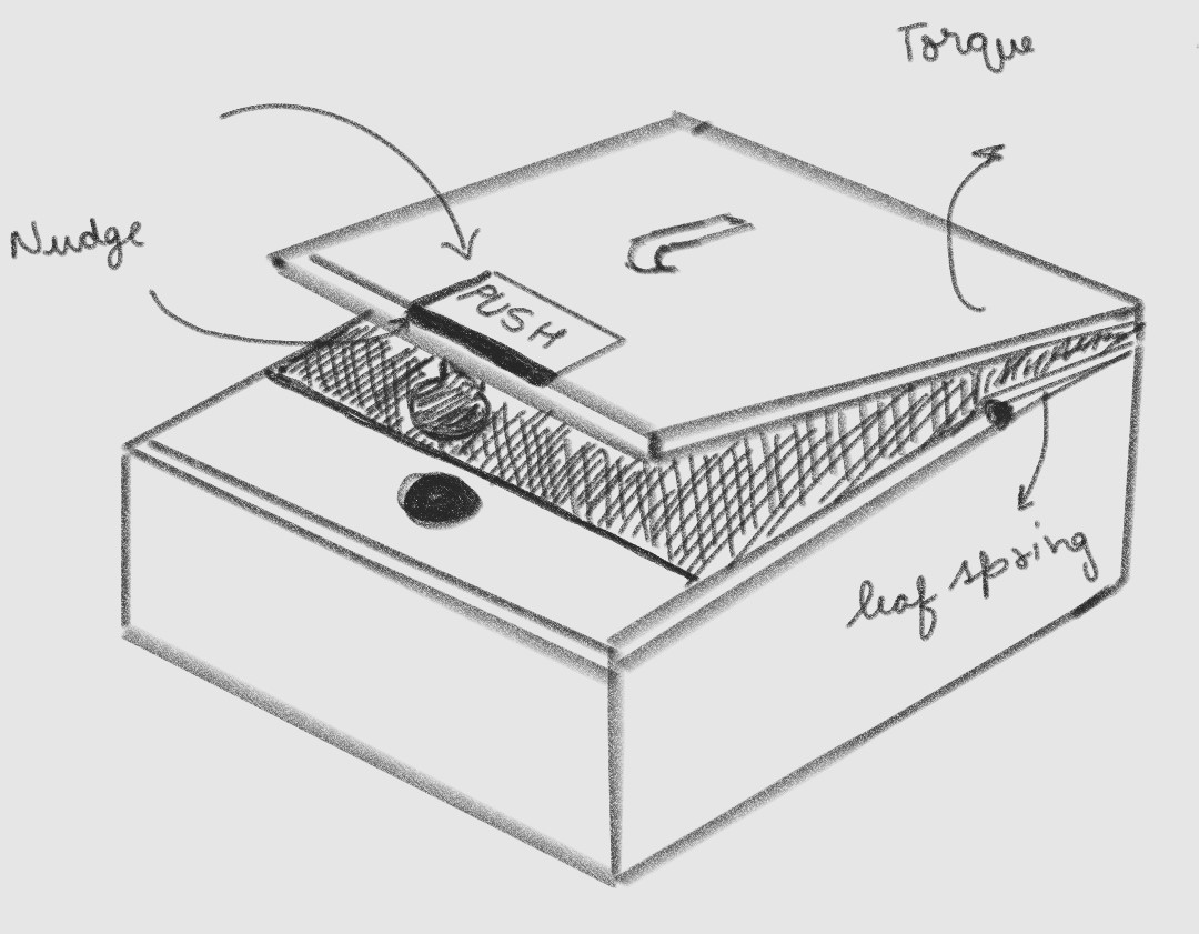
A1: Flat Prong
- Nudge-torque ejection with flat cantilever prongs
- Good conceptually but only offers momentary action
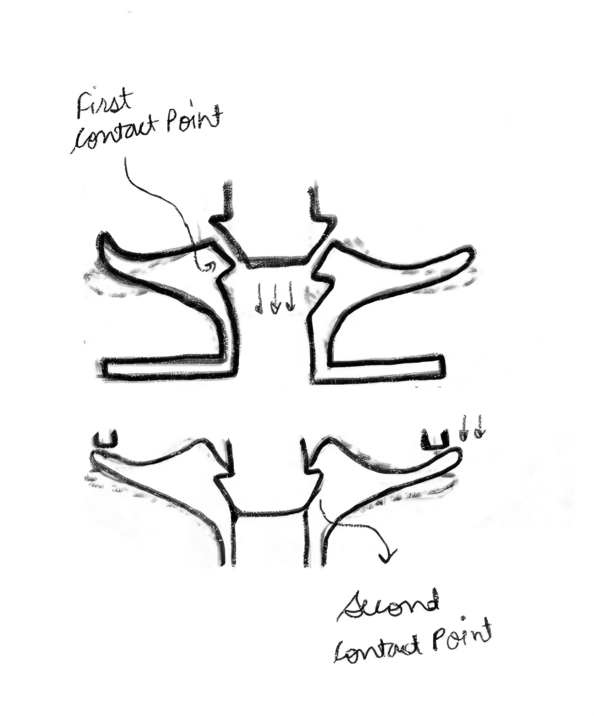
A2: Dual Contact
- Two-stage progressive engagement
- Solves timing issues of A1 but remains momentary-only
B: Spherical Wedge
- Rolling ball contact instead of sliding prongs to reduce friction
- Poor state retention and difficult assembly
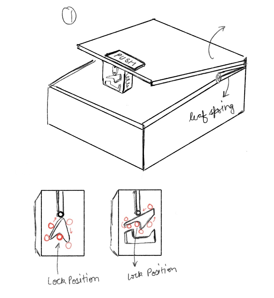
C: Groove Study
- Mapped out the autonomous bistable lock/unlock track logic
- Enables the "Service Mode" hands-free functionality
D: Final Mech
- Integrates vertical wedge geometry with lateral springs
- Cardioid track for true hands-free service mode
COMPONENT BREAKDOWN
Every component in the battery door assembly, with its engineering purpose, material specification, and critical dimensions.
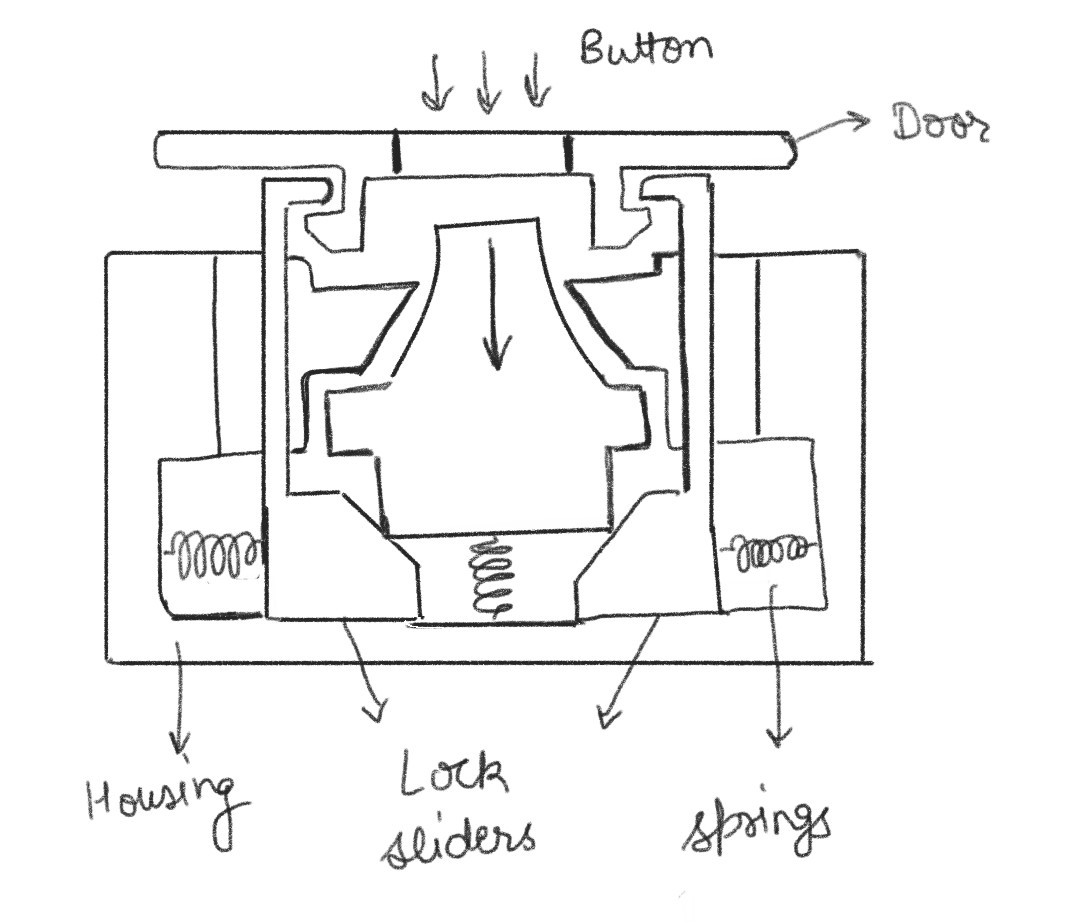
01 — Door
10% GF PC/ABS. Primary structural panel with rigid molded hooks. Houses mechanism, serves as seamless exterior.
02 — Wedge Button
PC/ABS. Translates Z-axis force into lateral latch retraction via 22.5° wedges. Houses cardioid heart-track.
03 — Micro-Latches (×2)
10% GF PC/ABS. Flexible sliding cantilever blocks engaging the hooks. They flex outward and do the locking work.
04 — Springs (×3)
High-Carbon Wire. 1× vertical return spring + 2× lateral coil springs (8.0N total). Drives reset snap and biasing.
05 — Follower Pin
304 SS Wire. Rides inside heart-track. Stepped depths ensure unidirectional travel. The mechanism's state machine.
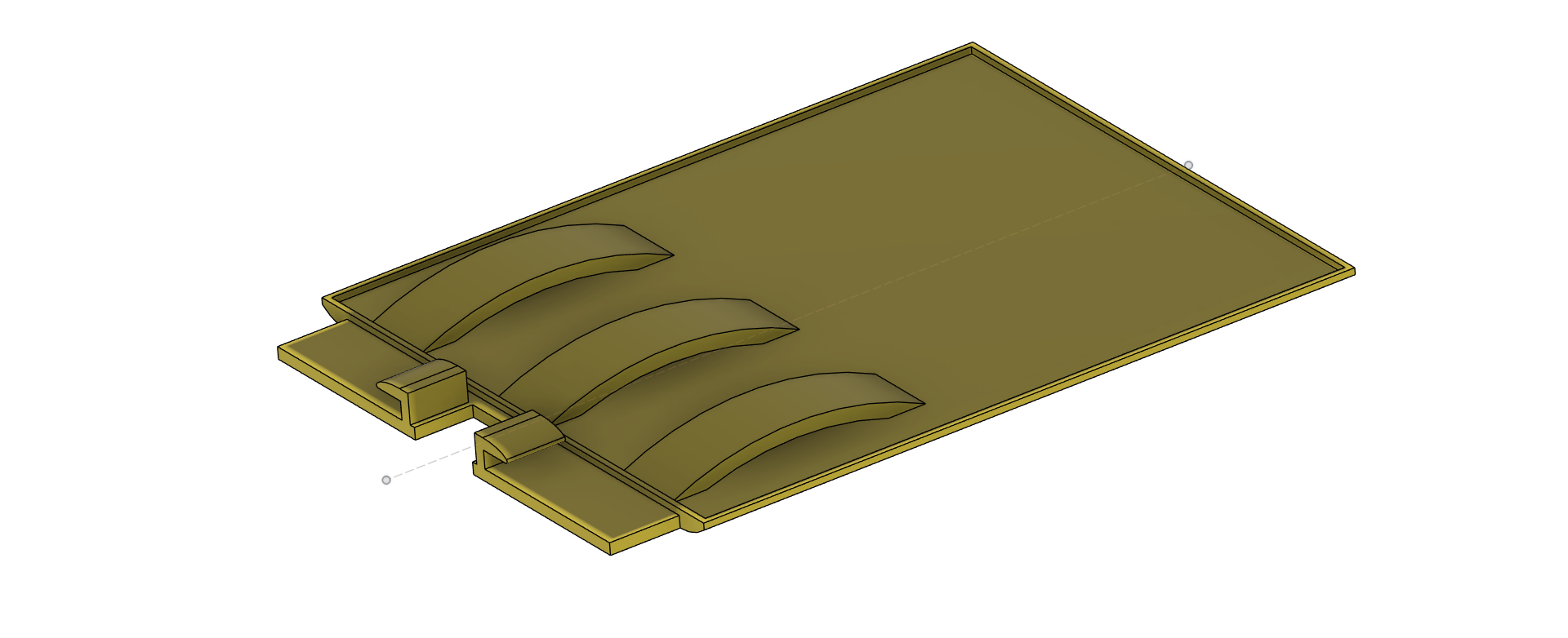
06 — Leaf Springs (×3)
Integrated into door. Provides 9.3 N ejection force at zero additional BOM cost. Dampening O-rings mute impact.
RESET RELIABILITY &
EJECTION DYNAMICS
Reset Click Verification
The vertical return spring must overcome track friction + button gravity to snap the button flush reliably:
The spring is 3.6× stronger than the resistance. Preload of 3.4 N (5mm compression × 0.68 N/mm) provides an authoritative, snappy "click."
Leaf Spring Assembly
Ejection Velocity (3-Battery Config)
Damping grease on leaf springs converts violent "fire" into a smooth, controlled rise.
STRUCTURAL INTEGRITY:
SHEAR LOAD MARGINS
Each hook in the entire model hangs 1.5mm outwards of their stem, which is 2mm wide. The end point of the hook is 0.5mm filleted, and the thickness of the hook is 1.3mm.
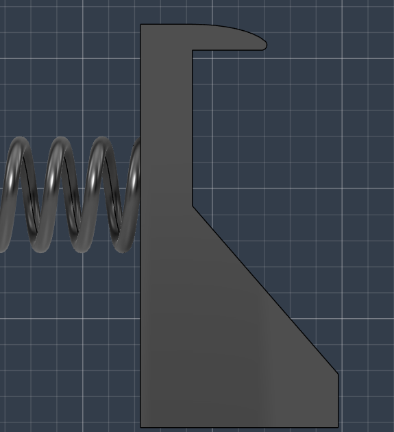
Curved Lead-in Advantage
The curved nature of the hooks fits the wedge securely and seamlessly guides the door hooks vertically into place during manual closing. Note: The door hooks are molded thick and rigid, forcing the mechanism's latch hooks to flex outward and do all the dynamic work.
SAFETY FACTOR
PC/ABS yields at ~50.0 MPa. At ~3.0 MPa applied stress, the hooks are practically indestructible in pure shear.
3D CAD [01] MECHANISM
ASSEMBLY
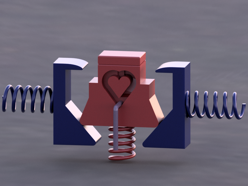
Rendered Isometric — Locked State
Shows the inverted pyramid button (red) sitting flush. The heart-shaped cardioid track holds the pin in the resting start position. Lateral coil springs fully drive latches inward to secure the door.
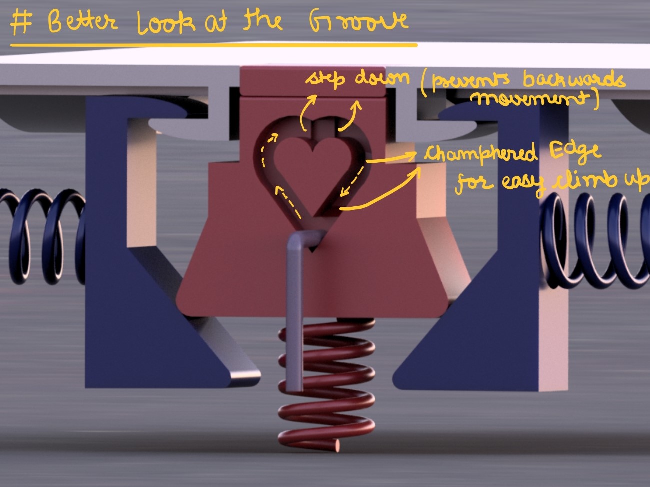
The Cardioid Heart-Track Groove
This is the 3D groove machined into the rear face of the wedge button. The follower pin rides through this track. Stepped depths at each valley ensure the pin can only travel forward through the lock→service→eject→lock cycle, never backwards. This is the physical "state machine" that gives the mechanism its bistable memory.
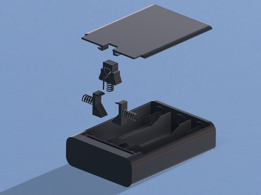
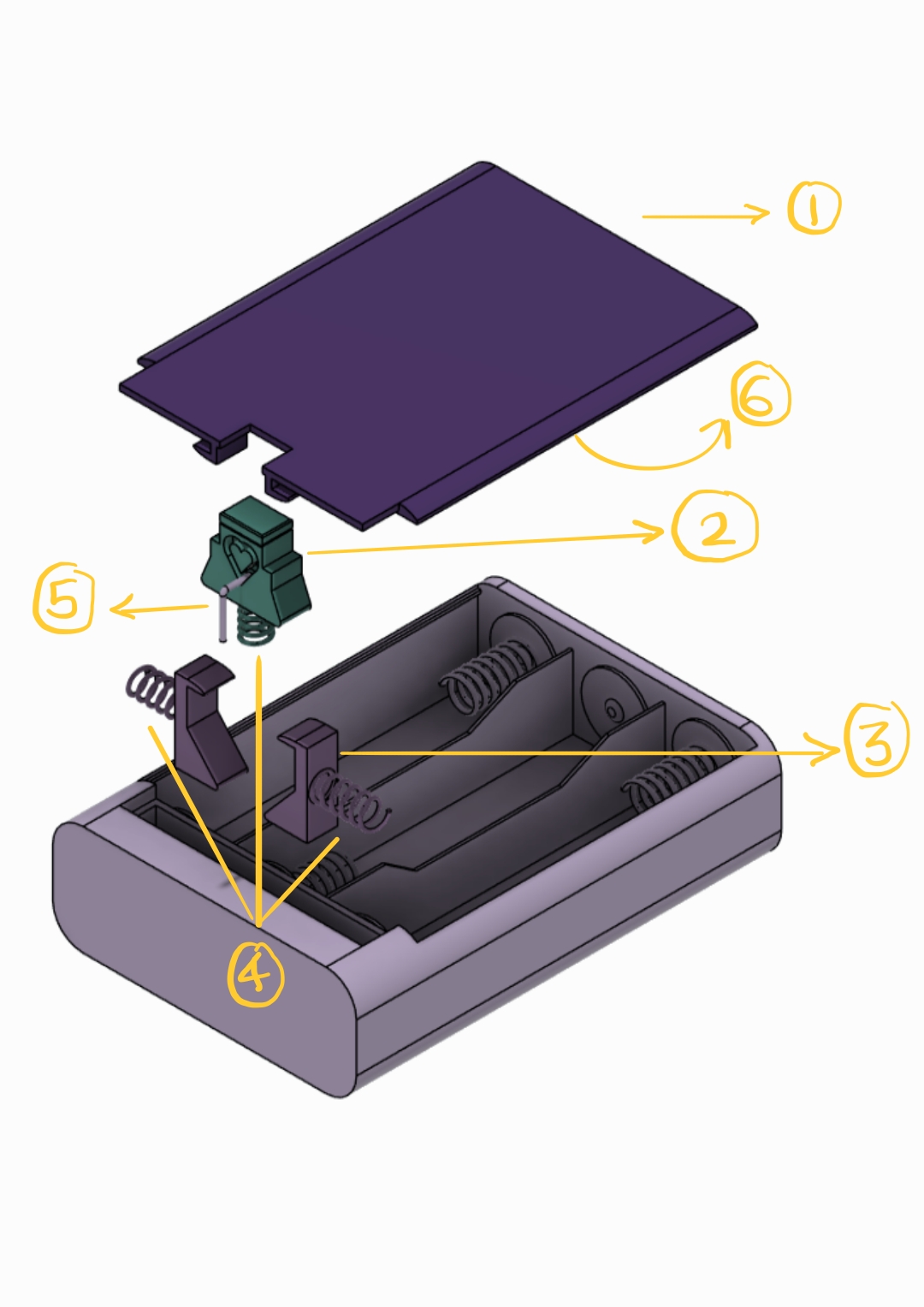
3D CAD EXPLODED
VIEW
Assembly Sequence
Assembly Sequence (Bottom-Up)
Button flush = Door Locked.
HOW IT WORKS
LOCKED
STATE
State 1: Resting & Secure
Securing The Mechanism
Relocking (2nd Click): A second press advances the follower pin to the next valley in the cardioid track, releasing the wedge. The vertical return spring snaps the button flush.
Closing the Door: The user pushes the door back down onto the chassis. The curved lead-in on the latch hooks guides the door smoothly past, temporarily deflecting the latches to secure the assembly.
HOW IT WORKS
UNLOCKED
STATE
State 2: Service Mode
Accessing Service Mode
Press the button (1st click): Pushing straight down forces lateral latches outward. The cardioid track captures the follower pin in its "service" valley, holding the button recessed.
Door pops open: With the mechanism retracted, the combined 32.64 N load from the conical/leaf springs pushes the door upward. Both hands are now free to swap batteries.
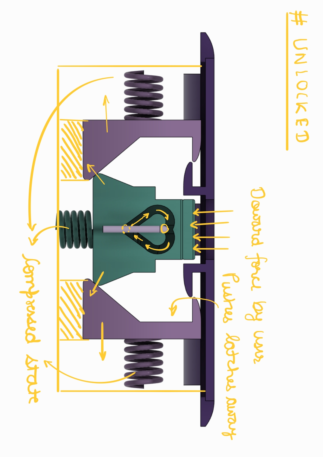
Button recessed = Service Mode Active.